What Is DFM for PEEK CNC machining (And Why It Matters)
Design for Manufacturability (DFM) means engineering a part so it can be produced reliably, repeatedly, and economically with the chosen process. For PEEK CNC machining, DFM is not a nice-to-have — it is the difference between a part that holds ±0.02 mm after weeks in storage and one that warps, cracks, or fails thread pull-out on the first assembly.
PEEK is different from metals and from common plastics. Its elastic modulus is low enough that thin walls spring back during cutting; its thermal conductivity is poor enough that heat accumulates at the tool edge; and its low moisture absorption actually works in your favor for dimensional stability. Every design rule below exists because PEEK responds to machining stress in ways aluminum, steel, or even POM simply do not.
If you are new to the material, start with our complete guide to what is PEEK machining and the peek material properties overview before applying these DFM rules.
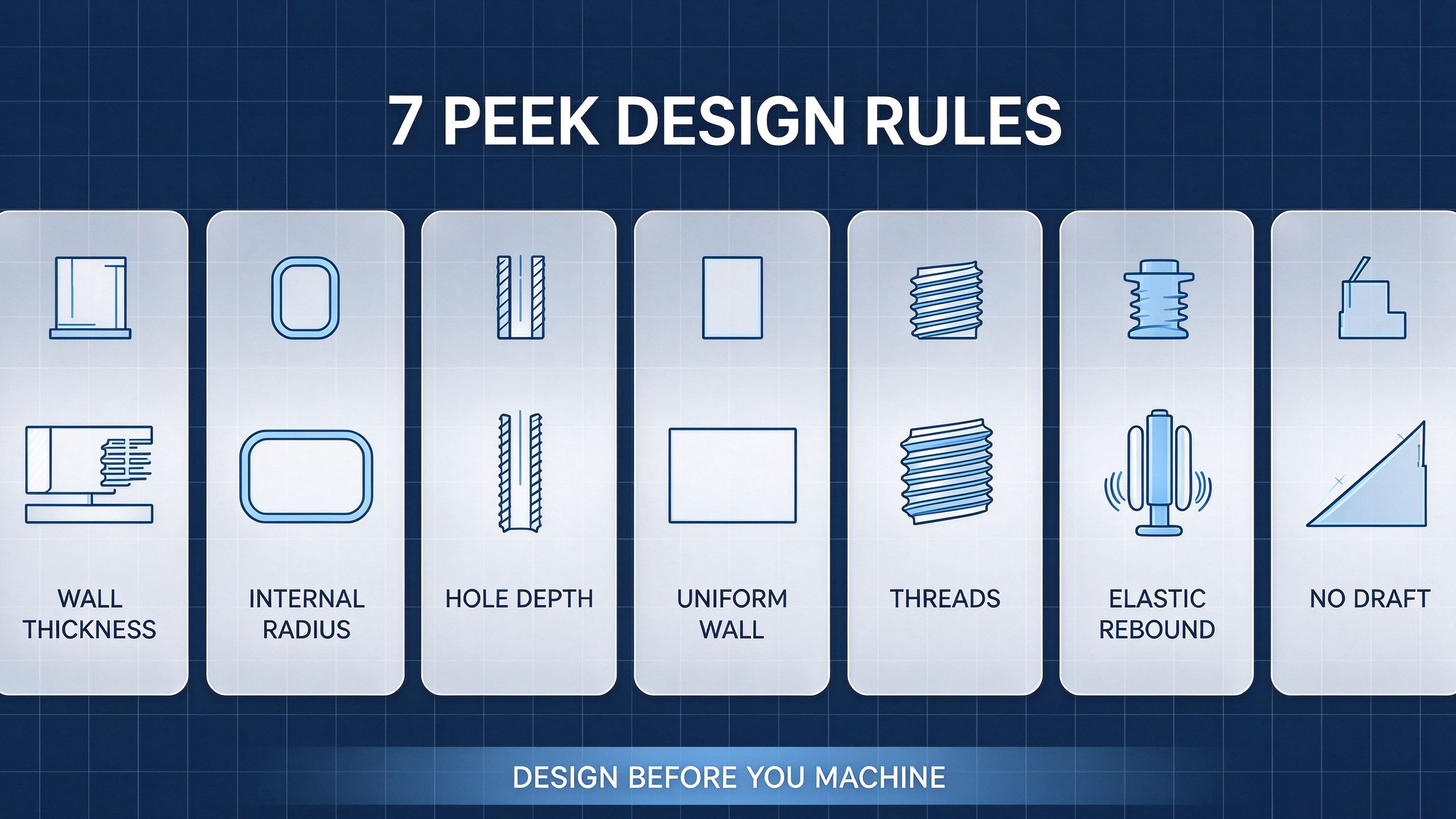
PEEK Design Guidelines: 7 Rules for Machinable PartsPEEK
Rule 1 — Keep walls thick enough.
A general minimum of 1.0–1.5 mm for unsupported walls, and 0.5–0.8 mm for short, supported features. Below these values, elastic rebound and cutting pressure cause deflection, chatter, and dimensional drift. Filled grades (CF30) hold thinner walls better because stiffness is roughly three times higher than unfilled PEEK.
Rule 2 — Use generous internal radii.
Avoid sharp internal corners. Design for R ≥ 1.0 mm where possible, and never below R 0.3 mm. Sharp corners create stress concentration, make chip evacuation harder, and force tool deflection that widens the tolerance band.
Rule 3 — Respect depth-to-diameter ratio.
For holes and pockets, keep depth ≤ 3× diameter with standard tooling; 4–5× is possible with reduced feed and pecking, but expect slower cycles and higher cost. Beyond that, consider splitting the part or specifying custom long-reach tooling.
Rule 4 — Keep wall thickness uniform.
Abrupt changes between thick and thin sections set up differential stress relief after machining and can cause delayed warpage. Blend thickness transitions with radii rather than steps.
Rule 5 — Design threads for PEEK, not for metal.
Threads down to M2 are feasible, but avoid sharp V-threads in thin walls. Use 60° unified or metric standard threads with a minimum engagement of 1.5–2× the thread diameter, and consider brass or stainless threaded inserts for M2.5–M6 features that will be repeatedly assembled.
Rule 6 — Plan for elastic rebound.
PEEK's modulus (roughly 3.5–4 GPa unfilled) means thin features deflect during cutting and spring back after the tool passes. If the drawing shows a tight slot or thin rib, expect the machinist to compensate with multiple passes and reduced depth of cut — design in tolerance accordingly.
Rule 7 — No draft angles needed (but no harm either).
Unlike injection molding, CNC machining does not require draft. Vertical walls are perfectly machinable, so do not add draft that will only weaken the part or complicate the print.
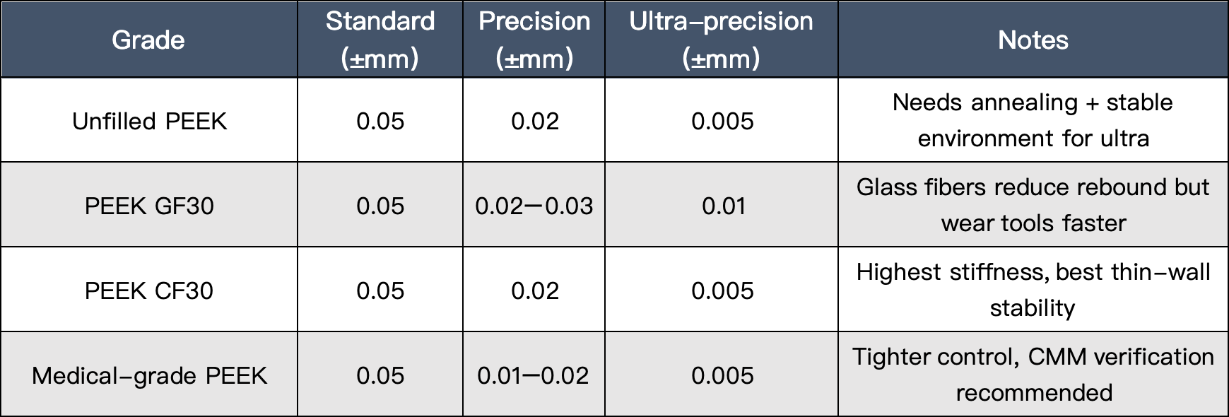
PEEK Machining Tolerance Recommendations by Grade
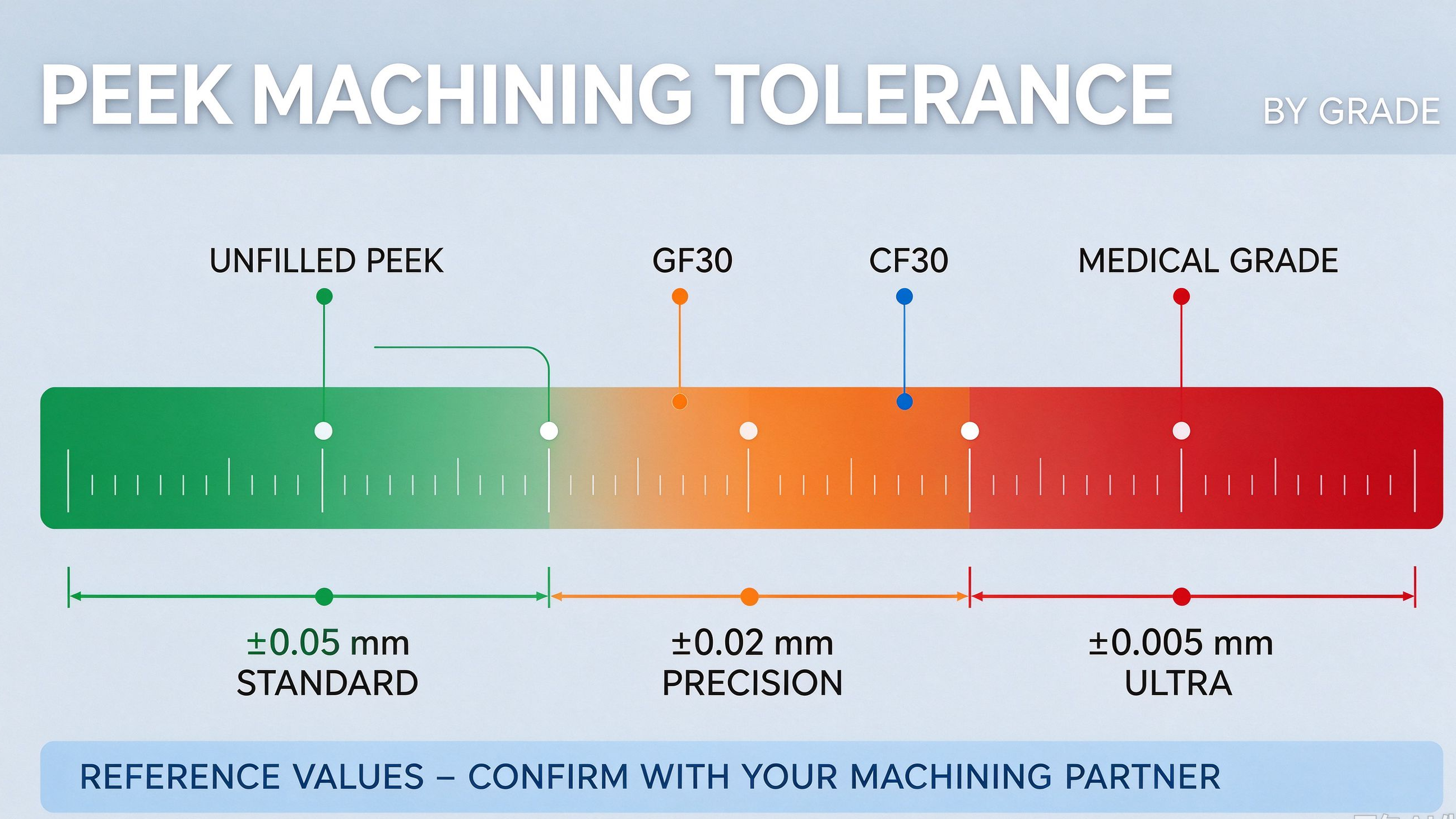
Tolerance is where PEEK DFM gets most expensive when done wrong. The table below shows what is realistically achievable on CNC-machined PEEK, by grade and by feature importance. Industry practice commonly separates three levels: standard, precision, and ultra-precision.
Three things push tolerance into the ultra range: annealing to release residual stress, climate-controlled inspection, and careful handling of thermal expansion during cutting.
PEEK's coefficient of thermal expansion is roughly 4.5–5 × 10⁻⁵ /°C below its glass transition (about 143 °C) — small but not zero, and machining heat alone can shift a thin feature by microns if the tool runs hot.
These values are reference figures; confirm capability with your machining partner before locking the print.
Functional vs Non-Functional Tolerances: Where to Save Cost
The fastest way to reduce PEEK part cost is not changing the material — it is cleaning up the tolerance callout. On every drawing, separate features into two groups:
Functional tolerances — mating surfaces, bearing bores, thread engagement zones, sealing faces. These deserve the precision budget (±0.01–0.02 mm where justified).
Non-functional tolerances — outside profiles, cosmetic edges, clearance holes, general surfaces. These should be released to ±0.05 mm or general machining tolerance (ISO 2768-m or similar).
Every feature pulled from ±0.05 mm down to ±0.02 mm roughly multiplies inspection effort and can add 10–20% to machining time through slower passes and additional finishing. On a PEEK part, where raw material already dominates cost, a bloated tolerance callout can push the quote up far more than the feature is worth. A simple rule: if it does not touch another part or carry a seal, leave it loose.
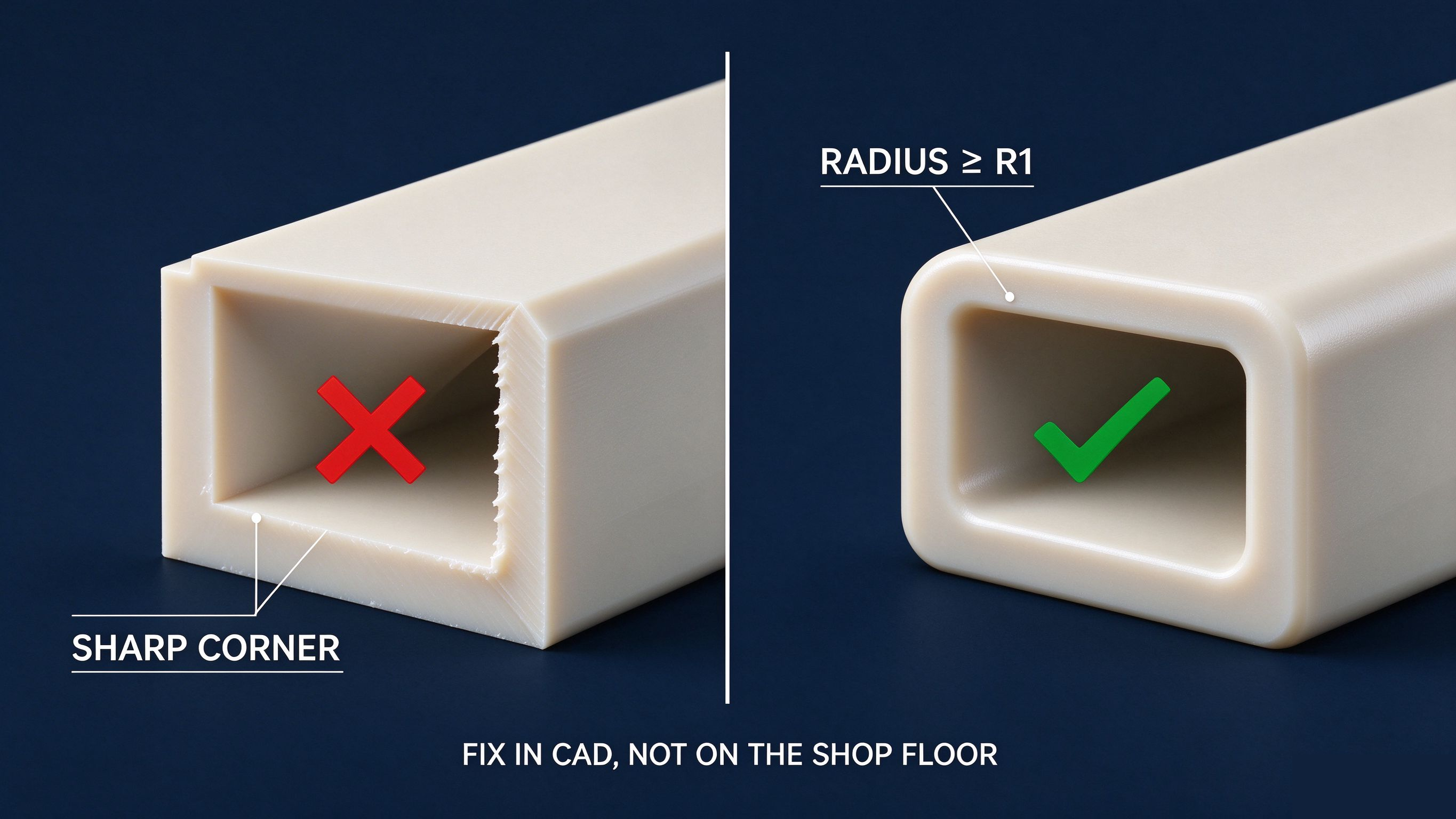
Common PEEK Design Mistakes (and How to Fix Them)
Mistake 1 — Sharp internal corners.
A 90° internal corner with zero radius concentrates stress and forces the machinist into tiny tooling. Fix: add R 0.5–1.0 mm; the part is stronger and faster to machine.
Mistake 2 — Abrupt wall thickness changes.
A 6 mm rib dropping to a 1 mm web sets up stress differential that shows up as warpage weeks later. Fix: blend the transition over at least 3× the thickness difference.
Mistake 3 — Deep, small-diameter holes.
A Ø1.5 mm hole 10 mm deep is a tool-breakage lottery. Fix: increase diameter, reduce depth, or redesign as a two-part assembly.
Mistake 4 — Unreasonable thread specifications.
Specifying M1.6 threads in a 2 mm wall, or blind threads with insufficient clearance for tap breakout. Fix: use M2+ minimum, specify thread depth with 1.5–2× engagement, and leave tap-clearance room.
Mistake 5 — Thin walls without support.
Large-area 0.5 mm walls vibrate, bow, and burn during cutting. Fix: add gussets, shorten the unsupported span, or switch to CF30 for stiffness.
When to Specify Annealing & Stress Relief on Your Drawing
Residual stress in PEEK comes from two places: the extruded or molded stock itself, and the heat and pressure of machining. Unrelieved stress shows up as warpage, delayed deformation, and micro-cracks — sometimes weeks after the part ships.
Specify annealing on the drawing when any of these are true:
The part holds precision tolerances (±0.02 mm or tighter) over a large surface
Thin sections are combined with thick sections
The part will run at elevated temperature in service
The material is unfilled PEEK, which carries the most residual stress
A typical anneal holds the part at roughly 150–200 °C (above the glass transition but below the melting range) for 2–4 hours depending on wall thickness, followed by slow cooling. The exact cycle depends on the grade and the supplier's datasheet — this is why we maintain a dedicated article on PEEK annealing and stress relief. On the drawing, add a note such as: "Stress-relieve after roughing, before final machining. Anneal: per material supplier datasheet."
In practice, the best process is to rough-machine, anneal, then finish — the sequence that lets the part relax before the final tolerances are cut. For a deeper look at the failure modes this prevents, see the cnc machining peek process article.
PEEK DFM Checklist Before You Send the Drawing
Run this checklist before your PEEK drawing goes to quoting — it catches 90% of the problems that cause rework:
Minimum wall thickness ≥ 1.0 mm (unsupported) / ≥ 0.5 mm (supported)? If thinner, note CF30 or add support ribs.
All internal corners have R ≥ 0.3 mm, preferably R ≥ 1.0 mm?
Hole depth ≤ 3× diameter (≤ 5× with note)? Thin-wall hole features called out with rebound compensation?
Wall thickness transitions blended, no abrupt steps?
Threads: M2 minimum, engagement 1.5–2× diameter, tap clearance provided? Inserts specified for repeated assembly?
Tolerances split: functional features tight, non-functional released to ±0.05 mm?
Annealing / stress relief note added where precision or thin+thick sections are involved?
Material grade specified by full trade name (e.g., PEEK 450G, 450GL30, 450CA30) so the shop buys the right stock?
Datums and inspection method (CMM vs gauge) agreed for the critical dimensions?
Edge conditions (sharp vs deburred vs radiused) stated for sealing and wear faces?
Q1. What is the minimum wall thickness for CNC machined PEEK?
Unsupported walls: 1.0–1.5 mm; short supported features: 0.5–0.8 mm; carbon-filled PEEK (CF30) can hold thinner walls due to higher stiffness.
Q2. What tolerance can CNC machining hold on PEEK?
Standard ±0.05 mm; precision ±0.01–0.02 mm; ultra-precision±0.005 mm with annealing, climate-controlled inspection, and controlled cutting heat.
Q3. Can PEEK parts be threaded? Will the threads strip?
Yes, threads down to M2 are feasible. Use standard 60° thread forms, 1.5–2× engagement, forming or sharp cutting taps, and threaded inserts for repeated assembly in thin walls.
Q4. What internal radius should I design for PEEK corners?
At least R 0.3 mm; R 1.0 mm or larger is recommended to avoid stress concentration and improve chip evacuation.
Q5. Why do machined PEEK parts warp after delivery?
Residual stress from stock and machining relaxes over time, causing delayed deformation. Prevent it by specifying annealing/stress relief, uniform wall thickness, and blended transitions.
Q6. Does CNC PEEK need draft angles?
No. Unlike injection molding, CNC machining cuts vertical walls without draft, so avoid adding draft that only weakens the part.
Ready to machine PEEK parts that hold tolerance from day one? Send us your 2D/3D drawing and material grade — we will return a free DFM review and a quotation within 24 hours. We machine virgin, GF30, CF30 and medical-grade PEEK with full material traceability, annealing control, and CMM inspection.
Email: konsdun.li@gmail.com ; liu@konsdun.com
WhatsApp: +86 133 9282 6147






 Phone
Comment
(0)