A metal 3D printed impeller is a rotating fluid-handling component produced through powder bed fusion or directed energy deposition rather than machining from billet or casting. For engineers designing pumps, compressors, turbines, and turbomachinery systems, additive manufacturing removes the geometric constraints of five-axis machining and casting cores, making conformal cooling channels, optimized blade curvature, and internal lattice structures directly manufacturable.
This guide explains how to design a metal 3D printed impeller that prints reliably, meets dimensional requirements, and survives real operating loads. It covers Design for Additive Manufacturing (DfAM) rules, material selection, achievable tolerances, post-processing, inspection, and supplier evaluation, based on production experience with aluminum, titanium, Inconel, and stainless steel builds.
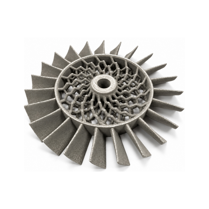
The turbine rotor shown above was printed with an internal lattice structure that reduced its mass by roughly 40 percent compared with a solid design of the same envelope, without changing its aerodynamic profile. That combination of fixed external geometry and free internal geometry is the central reason engineers choose additive manufacturing for rotating components.
Why Are Manufacturers Switching to Metal 3D Printed Impellers?
Manufacturers switch to metal 3D printed impellers because additive manufacturing solves three problems that conventional processes handle poorly: geometric complexity, multi-component assemblies, and low-to-medium production volumes. The decision is driven by engineering economics, not novelty.
Geometric freedom. Five-axis machining of a shrouded impeller from billet is possible but expensive: the tool access constraints force compromises in blade curvature, and every undercut requires a setup change. Casting can produce complex shapes but requires a core for internal passages, and cores impose minimum wall thicknesses and draft angles. Powder bed fusion builds the part layer by layer, so blade twist, internal cooling channels, and variable wall thickness are free.
Part consolidation. A conventional centrifugal compressor stage may consist of an impeller, an inducer, a shaft hub, and a wear ring, joined by welding, brazing, or fasteners. Each joint is a potential leak path, a stress concentration, and an assembly operation. A redesigned additive part can print the impeller and hub as a single monolithic component, eliminating the joint entirely. Field data from pump OEMs shows that consolidating a three-piece assembly into one printed part removes the most common warranty failure mode.
Economics at low volume. Casting tooling for an impeller costs tens of thousands of dollars and takes weeks to produce. For prototype runs, pilot builds, spare parts, or custom low-volume production, additive manufacturing eliminates that tooling investment. A prototype impeller can be printed, machined, and tested in three to five weeks, compared with three to five months for a cast alternative.
The business case does not hold at high volume. Once annual demand exceeds several hundred units of a simple geometry, machining or casting regains the cost advantage. Additive manufacturing wins where complexity, customization, or speed matter more than unit price.
What Is DfAM and Why Does It Matter for Impellers?
Design for Additive Manufacturing (DfAM) is the discipline of adapting a component design to the strengths and limits of the printing process, rather than translating a machined-part drawing directly into a build file. For impellers, DfAM is the difference between a successful first build and a cracked, distorted part that must be redesigned.
Four DfAM principles dominate impeller design:
Self-supporting geometry. Overhanging features below roughly 45 degrees from the horizontal build plane require support structures. On an impeller, the underside of the shroud and the hub taper are the typical trouble spots. Designers can orient the part to minimize supports, redesign sharp overhangs as fillets, or accept the supports and plan their removal with EDM or machining.
Powder removal. Closed internal channels must have drain holes for unfused powder. A shrouded impeller with internal cooling passages must be designed so that every cavity can be emptied after the build. Trapped powder adds weight, ruins balance, and can migrate into the process fluid in service.
Uniform wall thickness. Large differences between adjacent wall sections create thermal gradients during the build, which generate residual stress and distortion. On an impeller, the thick hub and thin blades are inherent to the design; the DfAM answer is to thin the hub with lattice or hollow sections rather than redesign the blades.
Minimum feature size. Laser powder bed fusion machines have a resolution limit of roughly 0.3 to 0.5 millimeters for features such as blade edges. Thin trailing edges that are below the process limit must be thickened in the design or finished by machining.
Each of these rules has a measurable consequence. Supports that cannot be removed without damaging a blade cost hours of labor. Trapped powder in a 200-millimeter impeller can exceed the allowable residual imbalance for the entire assembly. A hub that is too thick relative to the blades will warp enough to miss the bore tolerance. DfAM is not optionalâit is the engineering work that makes the print succeed.
Which Materials Work Best for Metal 3D Printed Impellers?
Material selection for a 3D printed impeller follows the same logic as for a conventionally made one: match the alloy to the temperature, corrosion environment, speed, and fatigue load, then confirm that the alloy prints well in the chosen process. The five most common choices:
| Alloy | Typical process | Best application | Print behavior |
|---|
| AlSi10Mg (aluminum) | LPBF | Low-temperature compressor impellers, lightweight prototypes | Excellent printability, good as-printed surface, moderate fatigue |
| Ti-6Al-4V (titanium) | LPBF, EBM | Aerospace and high-speed impellers, weight-critical designs | High strength-to-weight, excellent fatigue, higher cost |
| Inconel 718 (nickel alloy) | LPBF | Hot-section turbine impellers, high-temperature pumps | Very good printability, high-temperature strength, slow builds |
| 316L stainless steel | LPBF | General-purpose pump impellers, corrosion-resistant parts | Good printability, corrosion-resistant, moderate strength |
| 17-4PH stainless steel | LPBF | Higher-strength pump and marine impellers | Good printability, better strength than 316L after aging |
The table should be read as a starting point, not a verdict. Aluminum is easy to print but limited to roughly 150 degrees Celsius in sustained service. Titanium is light and strong but expensive and can be difficult to post-machine. Inconel 718 handles 700 degrees Celsius but costs five to ten times more per kilogram than 316L and builds more slowly. The right answer depends on the operating point of the machine the impeller serves.
One caution: printed properties differ from wrought properties. An as-built LPBF Inconel 718 part has lower fatigue life than the wrought alloy until it receives the standard solution and age heat treatment. Published material allowables from machined bar stock do not transfer directly to printed parts; use printed-part test data from the supplier or from published standards such as ISO/ASTM 52904.
How Do Support Structures and Powder Removal Work?
Support structures are sacrificial features that anchor the part to the build plate and conduct heat away from overhanging surfaces. On an impeller, supports typically attach to the hub bottom and to the underside of the shroud. The design questions are where to place them, how to minimize their footprint, and how to remove them without damaging the part.
The best strategy is orientation. Printing an impeller hub-down places the largest overhangâthe shroud undersideâat a steep angle, often above the self-supporting threshold. If that is not possible, the support contact area should be minimized by using thin, perforated support geometries that can be clipped or machined away. For internal passages, supports should be designed to be reachable by EDM wire or electrochemical machining.
Powder removal is a parallel constraint. A shrouded impeller with internal cooling channels contains enclosed cavities that hold unfused powder after the build. Each cavity needs at least one drain hole, ideally at the lowest point in the build orientation, large enough for powder to flow out under gravity or vibration. Holes can be plugged or welded shut after powder removal. Designers who skip this step discover it when the finished impeller rattles.
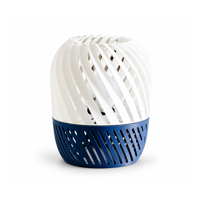
The housing above illustrates the same principle on a different part: a 3D printed enclosure with an open lattice that uses material only where it is structurally needed. The geometry that makes it light also makes it printable, because thin lattice walls dissipate heat evenly and require no supports in most orientations.
How Does Lattice Lightweighting Work in Rotating Components?
Lattice structures are internal networks of thin struts or gyroid surfaces that fill a volume with less material than a solid. In an impeller, the hub and shroud are the natural candidates for lattice infill because they carry structural load but do not contact the process fluid. A lattice hub can reduce part mass by 30 to 50 percent while preserving stiffness in the directions that matter for rotor dynamics.
The engineering benefit is rotational inertia. An impeller with a lighter hub accelerates faster, puts less load on the shaft bearings, and reduces the critical speed margin required from the rotor design. For turbochargers and high-speed compressors, this translates directly into faster transient response and lower bearing wear.
Three rules govern lattice design for rotating parts:
Keep the external skin intact. The aerodynamic surfaces of the blades and the sealing surfaces of the shroud must remain solid. The lattice lives inside.
Design for powder removal. Open-cell lattices such as gyroids or strut networks allow powder to drain through the lattice. Closed-cell lattices trap powder and are generally unsuitable.
Verify the fatigue performance. Lattice struts have lower fatigue strength than bulk material because of their surface finish. A lattice hub must be checked against the cyclic load spectrum of the machine, not just the static strength.
Topology optimization software can generate lattice or near-lattice structures automatically from a load case, but the output must still be checked for printability. A topology-optimized hub with struts thinner than the process limit will not print.
What Tolerances and Surface Finish Can Be Expected?
Realistic tolerances for a metal 3D printed impeller in the as-printed state are plus or minus 0.1 to 0.2 millimeters for features under 100 millimeters, and plus or minus 0.1 to 0.2 percent of the nominal dimension for larger parts. As-printed surface finish is rough by rotating-machinery standards: Ra 6 to 20 micrometers depending on orientation, process, and alloy.
These numbers mean that critical interfaces are always machined after printing. The typical workflow:
| Feature | As-printed capability | Post-machined capability |
|---|
| Shaft bore diameter and fit | ±0.15 mm, rough | IT6-IT7, Ra 0.4-0.8 µm |
| Blade aerodynamic surfaces | Ra 8-15 µm | Ra 1.6-3.2 µm after milling or polishing |
| Hub and shroud sealing faces | ±0.1-0.2 mm | ±0.02-0.05 mm, Ra 0.8-1.6 µm |
| Balancing surfaces and pads | ±0.1 mm | ±0.01 mm, balanced to G2.5 or G1.0 |
| Threaded or keyed features | Not recommended | Machined to standard fits |
The design implication is straightforward: leave machining stock on every interface that must meet a tight tolerance, and specify the finish in the drawing. A shaft bore printed to near-net size and machined to final dimension is the standard approach. Trying to print a bore to tolerance directly is a false economy.
Surface finish matters beyond fit. Blade roughness affects aerodynamic efficiencyâmeasurements on compressor impellers show that moving from Ra 10 µm to Ra 2 µm can recover two to four points of isentropic efficiency. For pump impellers, a smoother surface also reduces cavitation onset. The post-machining budget should include blade polishing or abrasive flow machining for the wetted surfaces.
What Post-Processing Steps Are Required?
A metal 3D printed impeller is not finished when the build ends. The standard post-processing chain includes heat treatment, support removal, machining, Surface Finishing, and balancing. Skipping any step produces a part that looks correct but fails in service.
Stress relief and heat treatment. Printed parts retain residual stress from the layer-by-layer build. A stress-relief cycleâtypically 650 to 850 degrees Celsius for aluminum and stainless steel, higher for Inconelârelaxes that stress before the part is removed from the build plate. High-performance alloys then receive solution and age treatments to reach their specified mechanical properties.
Hot isostatic pressing (HIP). For fatigue-critical aerospace and high-speed applications, HIP at high temperature and pressure closes internal porosity and improves fatigue life by 20 to 50 percent. HIP is optional for low-speed pump impellers but standard for turbine components.
Support removal and machining. Supports are removed by wire EDM or band saw, followed by machining of the bore, sealing faces, and any threaded features. The machining setup must reference the printed geometry accurately; a three-point probe or scanning routine is typical.
Surface finishing. Blades and wetted surfaces are polished, abrasive-flow machined, or electropolished to the required finish. Shot peening is sometimes added to improve fatigue resistance at the blade root.
Balancing. The finished impeller is dynamically balanced to the rotor specification, typically ISO 21940 grade G2.5 for industrial pumps and G1.0 or better for high-speed turbomachinery. A printed impeller with an internal lattice must be balanced after all machining is complete, because the lattice makes the mass distribution less predictable than a solid part.
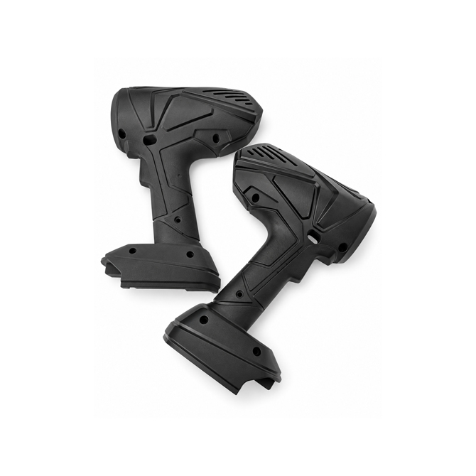
The drill housing above is a different application of the same workflow logic: a printed prototype that validates the geometry before committing to production tooling. The same sequenceâprint, machine the interfaces, verify, balanceâapplies whether the part is a consumer housing or a 50,000 rpm compressor wheel.
How Is a 3D Printed Impeller Inspected and Certified?
Inspection of a printed impeller combines conventional dimensional metrology with additive-specific checks. A typical quality plan includes:
Dimensional inspection. CMM measurement of the machined interfaces and 3D scanning of the blade surfaces against the CAD model. Scanning catches blade twist and profile errors that a CMM program based on discrete points can miss.
Non-destructive testing. Dye penetrant or fluorescent penetrant inspection for surface cracks on the blades and hub. For fatigue-critical parts, computed tomography (CT) scanning detects internal porosity and trapped powder. CT is the only reliable way to verify that internal channels are clear.
Mechanical testing. Tensile and fatigue coupons printed in the same build as the part, tested to confirm that the material properties meet specification. For rotating parts, a spin test or overspeed test may be specified to validate the part at 110 to 120 percent of rated speed.
Documentation. A first article inspection (FAI) report that records every measured dimension, the material batch, the machine parameters, and the test results. The FAI report is the traceability backbone for aerospace, medical, and regulated industrial applications.
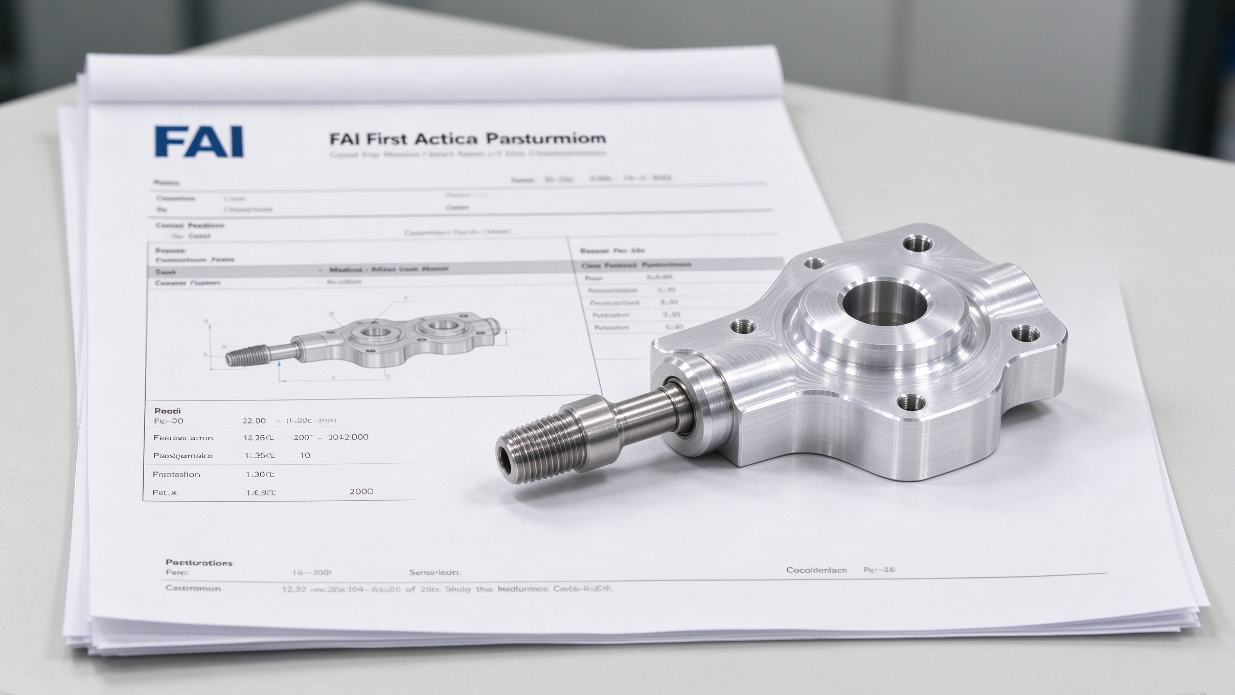
The FAI report above shows the level of documentation expected for precision parts: every dimension measured against the drawing, with the measurement method and result recorded. For additive parts, the report should also include the build orientation, layer thickness, and heat treatment batch.
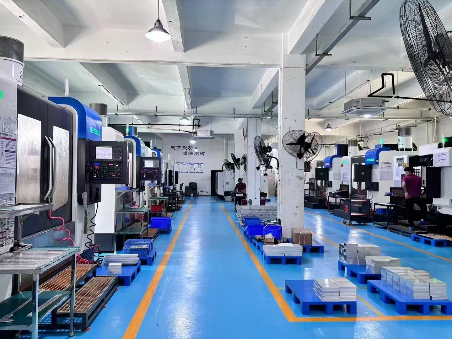
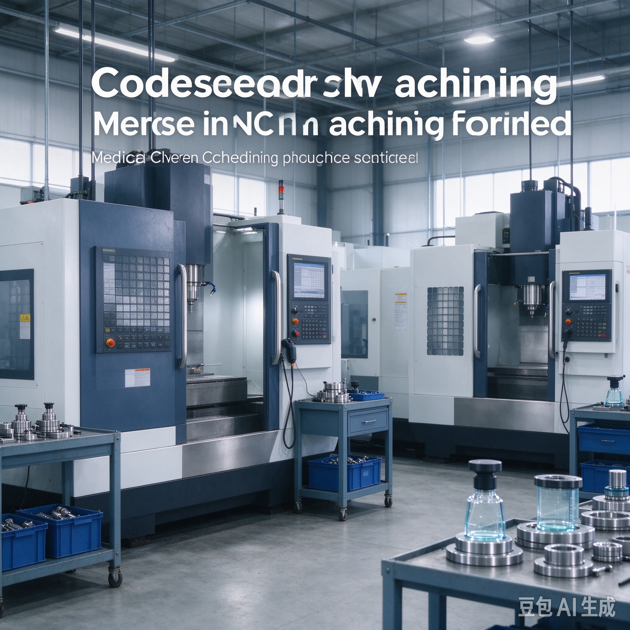
The production floor matters because post-processing quality is set by the machine shop, not the printer. A supplier that prints the part but outsources machining, balancing, and inspection to third parties adds lead time and loses control of the tolerances that matter most.
What Are the Main Application Areas?
Metal 3D printed impellers are established in five application areas:
Turbochargers. Compressor wheels benefit from lightweighting and complex blade geometry. Printed titanium wheels are in production for performance and motorsport applications.
Centrifugal pumps. Custom and low-volume pump impellers for chemical, marine, and industrial processes, where corrosion-resistant alloys and non-standard geometries are common.
Compressors and blowers. Impellers for process gas and air compressors, particularly where part consolidation reduces leak paths in high-pressure stages.
Aerospace turbomachinery. Fuel pump impellers, APU components, and experimental turbine stages, where the fatigue and temperature capability of Inconel and titanium justify the cost.
rapid prototyping. Functional impeller prototypes for wind tunnel, flow loop, or engine testing, reducing development cycles from months to weeks.
The pattern across all five is the same: additive manufacturing is chosen where geometry, volume, or lead time make conventional methods uncompetitive, not as a wholesale replacement for machining and casting.
How to Choose a Metal 3D Printing Partner?
Evaluate a supplier on five criteria:
Machine fleet and process control. The supplier should run current-generation LPBF or EBM machines with documented calibration and parameter control. Ask for a process qualification record, not just a brochure.
Material qualification. The supplier should have printed-part test data for the alloy you need, including tensile, fatigue, and fracture properties after the specified heat treatment.
In-house post-processing. Machining, balancing, heat treatment, and inspection should be in-house or tightly managed. Each handoff adds risk.
Engineering support. A good supplier reviews the design for printability before quoting, and proposes DfAM changes that improve the build. A supplier that prints the file as sent without comment is a red flag.
Traceability. FAI reports, material certificates, and machine logs should be standard deliverables, not extras.
For engineers evaluating whether a specific impeller is a good additive candidate, browse the Precision Machining and custom manufacturing capabilities or send a project enquiry with the operating conditions, target material, and annual volume. The enquiry should include the duty point, fluid, temperature, speed, and any regulatory requirements, because those determine the material and process selection.
Frequently Asked Questions About Metal 3D Printed Impellers
Can a 3D printed impeller match the strength of a machined one?
Yes, with the correct alloy and post-processing. A printed Inconel 718 impeller that receives solution and age heat treatment plus HIP can reach 90 to 100 percent of the wrought alloy's fatigue strength. The as-printed part is weaker; the post-processed part is not.
How long does it take to produce a metal 3D printed impeller?
A typical lead time is three to six weeks for a prototype and four to eight weeks for a production part, including heat treatment, machining, balancing, and inspection. The build itself takes one to five days depending on size.
What is the largest impeller that can be 3D printed?
Current production LPBF machines handle parts up to roughly 400 to 600 millimeters in diameter. Larger impellers can be printed in sections and joined, or produced by directed energy deposition, which has a larger envelope but lower resolution.
Is 3D printing cheaper than machining for impellers?
For a single complex prototype or a low-volume custom part, yes. For simple geometries at volumes above several hundred units per year, machining from billet is usually cheaper per part. The crossover depends on complexity and material.
Can existing impeller designs be 3D printed without changes?
Rarely. A design optimized for machining or casting usually violates DfAM rules on overhangs, wall thickness, or powder removal. A printability review and minor redesign are almost always required.
What is the typical surface finish of a printed impeller blade?
As-printed blades are Ra 6 to 20 micrometers. After polishing or abrasive flow machining, Ra 1.6 to 3.2 micrometers is achievable on the wetted surfaces.
Do printed impellers need to be balanced?
Yes. All rotating parts must be dynamically balanced to the application specification. Printed parts with internal lattice structures require balancing after final machining because their internal mass distribution is less uniform than a solid part.
Can internal cooling channels be printed inside an impeller?
Yes, and this is one of the strongest reasons to use additive manufacturing. Conformal cooling channels that follow the blade geometry are impossible to machine but routine to print, provided the channels have drain holes for powder removal.
Conclusion
A successful metal 3D printed impeller is the product of four disciplines working together: DfAM to make the part printable, material selection to match the operating environment, post-processing to reach the required tolerances and properties, and inspection to prove the result. The process rewards engineers who treat the design as a system decision rather than a drawing translation.
For teams evaluating additive manufacturing for an impeller, turbine rotor, or other rotating component, the practical first step is a printability review of the existing design against the rules in this guide. Custom titanium precision parts and precision aluminum CNC machined parts cover the complementary subtractive capabilities for projects that combine printed and machined features. To discuss a specific application, send an enquiry with the operating conditions and target geometry.






 Phone
Comment
(0)